Fill Out a Valid Megger Test Template
Guide to Writing Megger Test
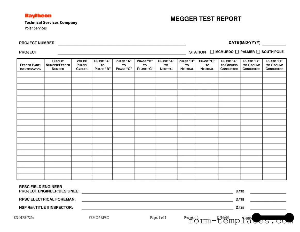
Filling out the Megger Test form is a straightforward process that ensures accurate recording of electrical testing data. Follow these steps carefully to complete the form correctly.
- Start by entering the PROJECT NUMBER at the top of the form.
- Next, indicate the PROJECT STATION from the options: McMurdo, Palmer, or South Pole.
- Fill in the DATE in the format M/D/YYYY.
- Identify the FEEDER PANEL by writing its name or number.
- Enter the CIRCUIT NUMBER/FEEDER NUMBER as applicable.
- Record the VOLTS/PHASE/CYCLES for the system being tested.
- For the voltage measurements, fill in the following fields:
- PHASE “A” TO PHASE “B”
- PHASE “A” TO PHASE “C”
- PHASE “B” TO PHASE “C”
- PHASE “A” TO NEUTRAL
- PHASE “B” TO NEUTRAL
- PHASE “C” TO NEUTRAL
- PHASE “A” TO GROUND
- PHASE “B” TO GROUND
- PHASE “C” TO GROUND
- Document the name of the RPSC FIELD ENGINEER responsible for the test.
- Next, have the PROJECT ENGINEER/DESIGNEE sign and date the form.
- Then, the RPSC ELECTRICAL FOREMAN should also sign and date the form.
- Finally, the NSF REP/TITLE II INSPECTOR must sign and date the document.
Document Breakdown
| Fact Name | Description |
|---|---|
| Project Identification | The form requires a unique project number and station name, ensuring clarity in record-keeping. |
| Date Requirement | It mandates the date in the format M/D/YYYY, promoting consistency across documentation. |
| Voltage Measurements | Measurements between phases and to neutral and ground are essential for safety assessments. |
| Responsible Parties | Signatures from the RPSC field engineer, project engineer, and electrical foreman are required, ensuring accountability. |
| Governing Law | This form is governed by state electrical safety regulations, which vary by state. |
FAQ
What is the purpose of the Megger Test form?
The Megger Test form is used to document the results of insulation resistance testing on electrical systems. This testing helps ensure that electrical equipment is safe and functioning properly. By measuring the insulation resistance, engineers can identify potential issues that could lead to electrical failures or hazards.
What information is required on the Megger Test form?
The Megger Test form requires several key pieces of information, including:
- Project number
- Project station
- Date of testing
- Feeder panel identification
- Circuit number or feeder number
- Voltage, phase, and cycles
Additionally, it includes test results for various phase-to-phase and phase-to-neutral measurements, as well as details about the personnel involved in the testing.
How are the test results recorded on the form?
Test results are recorded in specific fields corresponding to the various measurements taken. For example, the form includes sections for recording insulation resistance between different phases (e.g., Phase “A” to Phase “B”) and to neutral or ground. Each measurement is documented clearly, ensuring that all data is easily accessible for review and analysis.
Who should sign the Megger Test form?
Several individuals should sign the Megger Test form to verify the accuracy of the results. Typically, the following personnel are required to provide their signatures:
- RPSC field engineer
- Project engineer or designee
- RPSC electrical foreman
- NSF representative or title II inspector
This multi-signature requirement helps ensure accountability and thoroughness in the testing process.
What should be done with the completed Megger Test form?
Once the Megger Test form is completed and signed, it should be filed according to the project’s documentation procedures. Keeping a record of the test results is essential for future reference and compliance with safety regulations. It may also be used for audits or inspections by regulatory bodies.
Fill out Other Forms
Parent Permission Form - Signing this form indicates trust in the event's organizers.
The California Vehicle Purchase Agreement is a crucial document that outlines the terms and conditions of a vehicle sale between a buyer and a seller. This form ensures that both parties are aware of their rights and obligations, providing a clear framework for the transaction. Understanding this agreement is essential for a smooth and legally compliant vehicle purchase in California, and you can find the necessary documentation at californiadocsonline.com/vehicle-purchase-agreement-form/.
What Is Form 940 - Form 940 includes instructions on how to claim credits for state unemployment taxes.
Workplace Incident Report - Document the employee's condition after treatment.
Megger Test Example
MEGGER TEST REPORT
PROJECT NUMBER
PROJECT |
|
STATION |
DATE (M/D/YYYY)
MCMURDO 
 PALMER
 SOUTH POLE
FEEDER PANEL IDENTIFICATION
CIRCUIT
NUMBER/FEEDER
NUMBER
VOLTS/
PHASE/
CYCLES
PHASE “A”
TO
PHASE “B”
PHASE “A”
TO
PHASE “C”
PHASE “B”
TO
PHASE “C”
PHASE “A”
TO
NEUTRAL
PHASE “B”
TO
NEUTRAL
PHASE “C”
TO
NEUTRAL
PHASE “A”
TO GROUND CONDUCTOR
PHASE “B”
TO GROUND CONDUCTOR
PHASE “C”
TO GROUND CONDUCTOR
RPSC FIELD ENGINEER |
|
|
|
|
|
|
PROJECT ENGINEER/DESIGNEE: |
|
|
|
|
DATE |
|
RPSC ELECTRICAL FOREMAN: |
|
|
|
|
DATE |
|
NSF REP/TITLE II INSPECTOR: |
|
|
|
|
DATE |
|
FEMC / RPSC |
Paget 1 of 1 |
Revision 1 |
11/16//06 |
Approved by Wayne L. Cornell |
||